- 您现在的位置:买卖IC网 > Sheet目录17380 > SP6123EB (Exar Corporation)EVAL BOARD FOR SP6123
ABSOLUTE MAXIMUM RATINGS
These are stress ratings only and functional operation
of the device at these ratings or any other above those
indicated in the operation sections of the specifications
below is not implied. Exposure to absolute maximum
rating conditions for extended periods of time may
affect reliability.
V CC ....................................................................................................... 7V
BST .................................................................. 13.2V
BST-SWN .............................................................. 7V
All other pins ................................ -0.3V to V CC + 0.3V
Peak Output Current < 10 μ s
GH,GL .................................................................. 2A
Storage Temperature ........................ -65 ° C to 150 ° C
Power Dissipation
Lead Temperature (Soldering, 10 sec) ............ 300 ° C
ESD Rating. ................................................ 2kV HBM
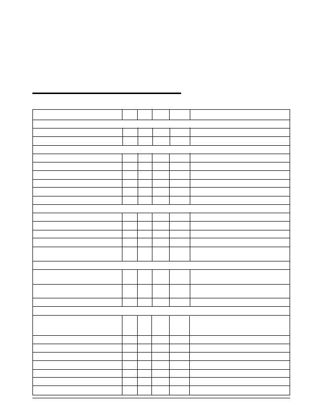
ELECTRICAL CHARACTERISTICS
Unless otherwise specified: 0 ° C < T A < 70 ° C, 3.0V < V CC < 5.5V, C COMP = 22nF, CGH = CGL = 3.3nF, V FB = 0.8V,
SWN = GND=0V, typical value for design guideline only.
PARAMETER
MIN
TYP MAX
UNITS
CONDITIONS
QUIESCENT CURRENT
V CC Supply Current
V CC Supply Current (Disabled)
0.5
30
1.0
60
mA
μ A
No Switching
COMP = 0V
ERROR AMPLIFIER
Error Amplifier Transconductance
0.6
mS
COMP Sink Current
COMP Source Current
15
15
35
35
60
60
μ A
μ A
V FB = 0.9V, COMP = 0.9V, No Faults
V FB = 0.7V, COMP = 2V
COMP Output Impedance
V FB Input Bias Current
3
100
M ?
nA
Error Amplifier Reference
0.788 0.8
0.812
V
Trimmed with Error Amp in Unity Gain
OSCILLATOR & DELAY PATH
Internal Oscillator Frequency
Internal Oscillator Frequency
Max. Controlled Duty Cycle
Minimum Duty Cycle
Minimum GH Pulse Width
270
450
90
300
500
93
100
330
550
0
250
kHz
kHz
%
%
ns
SP6123
SP6123A
Comp=0.7V
V CC > 4.5V, Ramp up COMP voltage until
GH starts switching
CURRENT LIMIT
Internal Current Limit Threshold
160
200
240
mV
V CC - V SWN ; Temp = 25 ° C;
V BST - V CC > 2.5V
Current Limit Threshold
Temperature Coefficient
Current Limit Time Constant
SOFT START, SHUTDOWN, UVLO
Internal Soft Start Slew Rate
0.34
15
%/C
us
SP6123A
SP6123
COMP Discharge Current
0.2
0.1
185
0.60
0.3
0.95
0.6
V/ms
V/ms
μ A
COMP = 0.5V, Fault Initiated
COMP Clamp Voltage
0.55 0.65
0.75
V
V FB = 0.9V
COMP Clamp Current
10
30
65
μ A
COMP = 0.5V, V FB = 0.9V
Shutdown Threshold Voltage
0.29 0.34
0.39
V
Measured at COMP Pin
Shutdown Input Pull-up Current
V CC Start Threshold
V CC Stop Threshold
2
2.63
2.47
5
2.8
2.7
10
2.95
2.9
μ A
V
V
COMP = 0.2V, Measured at COMP pin
Date: 9/13/04
SP6123 Low Voltage, Synchronous Step Down PWM Controller
2
? Copyright 2004 Sipex Corporation
发布紧急采购,3分钟左右您将得到回复。
相关PDF资料
MAX4825ETP+T
IC RELAY DRIVER 8CHAN 20-TQFN
MAX4822ETP+T
IC RELAY DRIVER 8CHAN 20-TQFN
R1S8-1505/P-R
CONV DC/DC 1W 15VIN 05VOUT
SP6121EB
EVAL BOARD FOR SP6121
A9CCA-0408F
FLEX CABLE - AFG04A/AF04/AFG04A
R1S-2409/P-R
CONV DC/DC 1W 24VIN 09VOUT
SP6120EB
EVAL BOARD FOR SP6120
ASPI-6045S-330M-T
INDUCTOR POWER 33UH 6045 SMD
相关代理商/技术参数
SP6123EN-L
制造商:Exar Corporation 功能描述:IC BUCK CONTROLLER LOW VOLT 300KHZ
SP6125
制造商:SIPEX 制造商全称:Sipex Corporation 功能描述:High-Voltage, Step Down Controller in TSOT6
SP6125EB
功能描述:电源管理IC开发工具 Eval Board for SP6125 Series
RoHS:否 制造商:Maxim Integrated 产品:Evaluation Kits 类型:Battery Management 工具用于评估:MAX17710GB 输入电压: 输出电压:1.8 V
SP6125EK1L
制造商:SIPEX 制造商全称:Sipex Corporation 功能描述:High-Voltage, Step Down Controller in TSOT6
SP6125EK1-L
功能描述:DC/DC 开关控制器 RoHS:否 制造商:Texas Instruments 输入电压:6 V to 100 V 开关频率: 输出电压:1.215 V to 80 V 输出电流:3.5 A 输出端数量:1 最大工作温度:+ 125 C 安装风格: 封装 / 箱体:CPAK
SP6125EK1-L/TR
功能描述:电源管理IC开发工具 High-Voltage Step Down Controller RoHS:否 制造商:Maxim Integrated 产品:Evaluation Kits 类型:Battery Management 工具用于评估:MAX17710GB 输入电压: 输出电压:1.8 V
SP6125EK1L/TR1
制造商:SIPEX 制造商全称:Sipex Corporation 功能描述:High-Voltage, Step Down Controller in TSOT6
SP6126
制造商:SIPEX 制造商全称:Sipex Corporation 功能描述:Evaluation Board Manual
